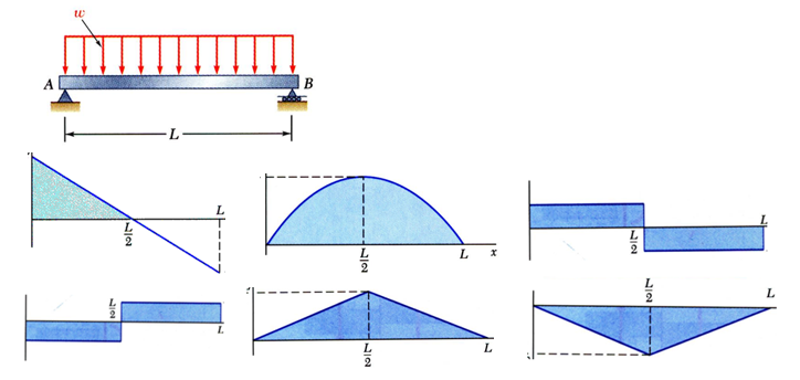
Relationship between shear and bending moment: 26ĭividing by Dx and taking the limit as Dxà0, the above two equations become: Regions of distributed load: Slope of moment diagram at each point = shear at each point Slope of shear diagram at each point = distributed load intensity at each point 27ģ0 = The previous equations become: Area under shear diagramĬhange in shear Area under distributed load change in moment =ģ4 Bending deformation of a straight member

Straight horizontal line y = c y = mx + c y=3x + 3 y=-3x + 3 y = ax2 + bx +c y=3x2 + 3 y=-3x2 + 3Ģ6 Graphical method Relationship between load and shear: Total force = area of distributed load (W : height and L: length) Point of action: center point of the areaġ9 Solve it Draw the shear and moment diagrams the beam:Ģ3 x=0 V= 12 kN x=4 V=-20 kN x=0 M= 0 kN x=4 V=-16 kN x=4 V= 16kN x=6 V= 0 kN x=4 V= -16kN x=6 V= 0 kN V = -9 kN F x M=-9x Sign convention: M= -9x kNm X=0: M= 0 X=3: M=-27kNmġ0 At cross section A-A At section A-A V=9kN M=X Xġ1 Example 2 1) Find all the external forcesġ2 Moment equilibrium Force equilibrium Moment equilibrium Force equilibriumġ4 Solve it Draw the shear and moment diagrams for simply supported beam.ġ6 Distributed Load For calculation purposes, distributed load can be represented as a single load acting on the center point of the distributed area. Type of Beams Statically Indeterminate Continuous Beam Propped Cantilever Beam Fixed Beamħ Example 1 A B M V F Equilibrium equation for 0 x 3m:Ĩ Shear Diagram M V F x Sign convention: V= -9kN Lecture 1ĩ Shear Diagram F M=-9x Sign convention: M= -9x kNm X=0: M= 0 Statically Determinate Simply Supported Beam Overhanging Beam Cantilever Beam

Similarly, the shear and moment diagrams show the internal shear and moment acting on the membersĤ Type of Beams Simply Supported Beam Overhanging Beam Cantilever Beam 1 Bending Shear and Moment Diagram, Graphical method to construct shearĪnd moment diagram, Bending deformation of a straight member, The flexure formulaĪxial load diagram Torque diagram Both of these diagrams show the internal forces acting on the members.


 0 kommentar(er)
